Tutorial
This tutorial provides a good starting point for learning how to use the Structurizr DSL. It will use the Structurizr playground and doesn’t require any special tooling to be installed.
1. System context
Let’s start the tutorial with a basic example of how to use the DSL. The starting point is to define a Structurizr workspace, which itself is a wrapper for a model (where we define elements and relationships) and a set of views (where we define the views that will ultimately be rendered as diagrams).
workspace "Name" "Description" {
}
The model keyword can be used to define our software architecture model, which in this example comprises a person named “User” (assigned to an identifier u) and a softwareSystem named “Software System” (assigned to an identifier ss). A relationship is then defined between the user and the software system using the -> symbol, with a description of “Uses”.
workspace "Name" "Description" {

    model {
        u = person "User"
        ss = softwareSystem "Software System"

        u -> ss "Uses"
    }

}
We can then define a single system context view, with the software system ss being the scope of this view.
workspace "Name" "Description" {

    model {
        u = person "User"
        ss = softwareSystem "Software System"

        u -> ss "Uses"
    }

    views {
        systemContext ss "Diagram1" {
            include *
        }
    }

}
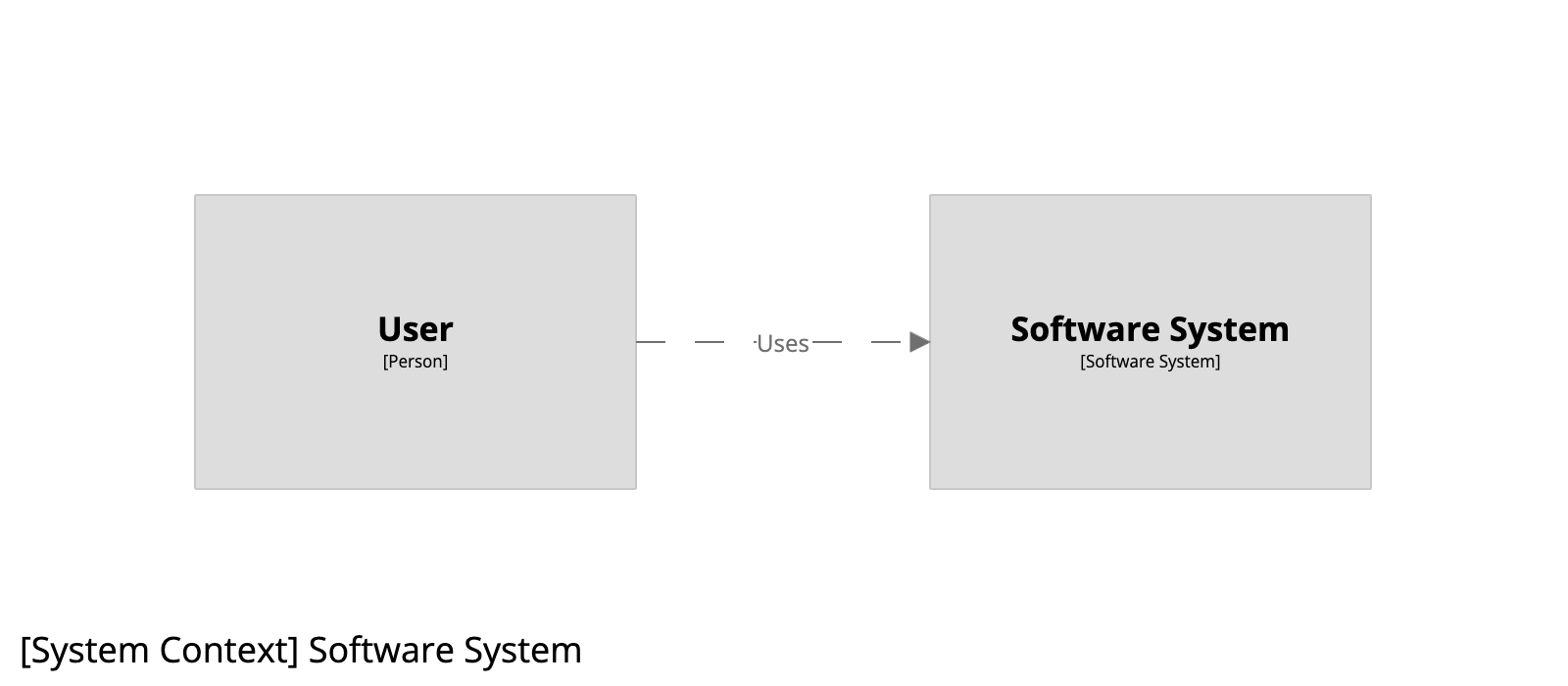
The include * statement says, “include the software system that is the scope of this view, along with any people and software systems that have a direct relationship to/from it”. Diagram1 is a unique diagram identifier/key that can be used to reference the diagram, for example, via the Structurizr Server diagram embed feature.
Running this example via the Structurizr playground (click the image below) results in the following diagram.
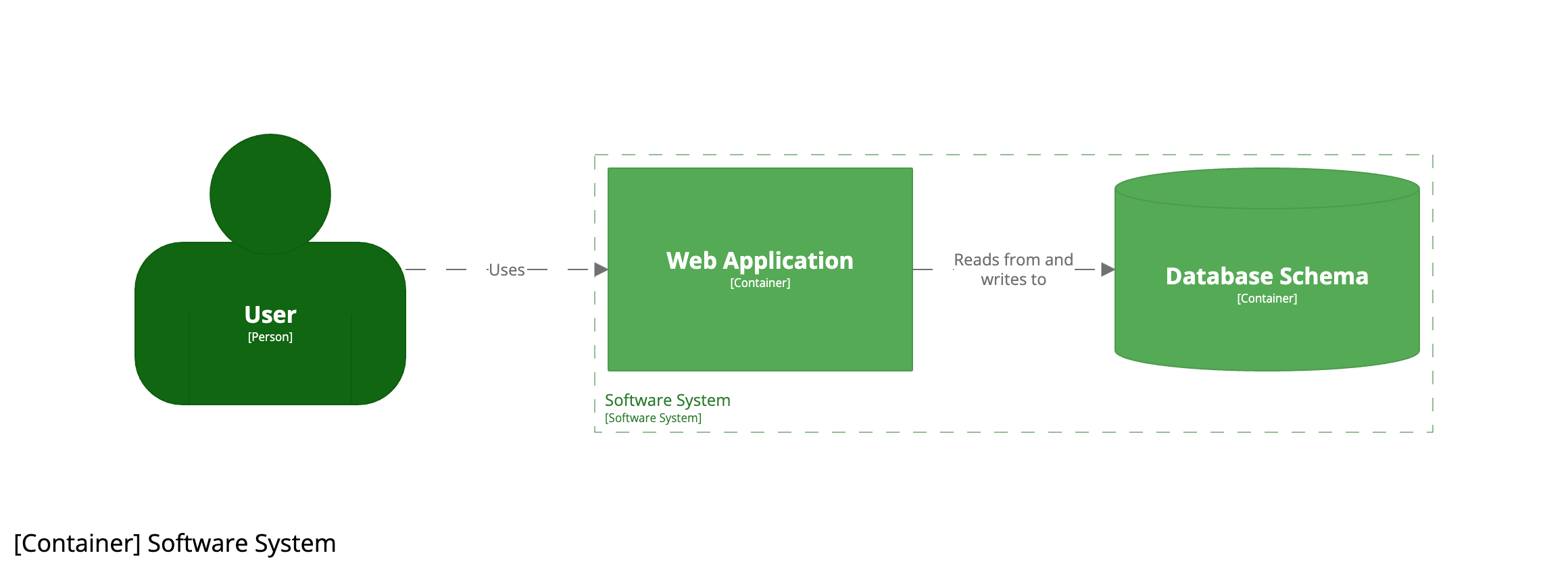
2. Containers
Next we can define the containers (applications and data stores) that make up our software system, by adding a couple of container definitions nested inside the software system (inside the curly braces). We can also define a relationship from the user to the web application, and from the web application to the database.
!identifiers hierarchical is used to allow us to refer to those containers via their fully qualified identifier.
workspace "Name" "Description" {

    !identifiers hierarchical

    model {
        u = person "User"
        ss = softwareSystem "Software System" {
            wa = container "Web Application"
            db = container "Database Schema" {
                tags "Database"
            }
        }

        u -> ss "Uses"
        u -> ss.wa "Uses"
        ss.wa -> ss.db "Reads from and writes to"
    }

    views {
        systemContext ss "Diagram1" {
            include *
        }
    }

}
The model is non-visual, so we need to define a container view, again with the software system ss being the scope of this view.
workspace "Name" "Description" {

    !identifiers hierarchical

    model {
        u = person "User"
        ss = softwareSystem "Software System" {
            wa = container "Web Application"
            db = container "Database Schema" {
                tags "Database"
            }
        }

        u -> ss "Uses"
        u -> ss.wa "Uses"
        ss.wa -> ss.db "Reads from and writes to"
    }

    views {
        systemContext ss "Diagram1" {
            include *
        }

        container ss "Diagram2" {
            include *
        }
    }

}
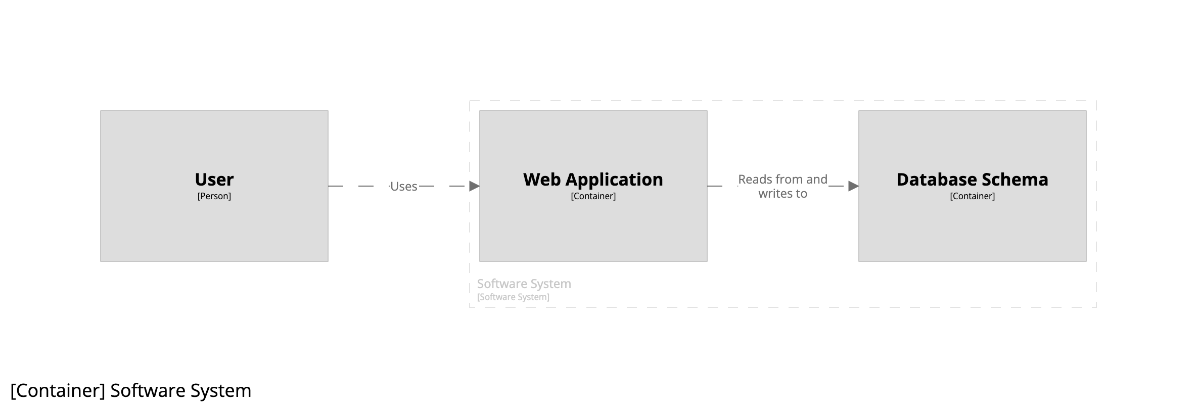
The include * statement now says, “include the containers inside the software system that is the scope of this view, along with any people and software systems that have a direct relationship to/from them”.
The example DSL creates two diagrams. First we have the system context diagram as before.

And if you double-click on the software system, you’ll navigate to the container diagram.
3. Implied relationships
“Don’t repeat yourself” (DRY) is something that we always tell ourselves as software developers, yet that’s essentially what we’ve done with the relationship from the user to the software system, and from the user to the web application.
        u -> ss "Uses"
        u -> ss.wa "Uses"
        ss.wa -> ss.db "Reads from and writes to"
The Structurizr DSL has a feature named implied relationships, which provides a way to reduce the number of relationships that you need to explicitly define in your DSL files. In this example, we can remove the first relationship definition, leaving only the latter two.
        u -> ss.wa "Uses"
        ss.wa -> ss.db "Reads from and writes to"
The resulting diagrams are the same. There is an explicit relationship from the user to the web application, and because the web application is a container inside the software system, there is an implicit (or implied) relationship between the user and the software system itself.

4. View expressions
Both of the view definitions use the include * statement, which provides a convenient way to include a default set of elements that readers may want to see. But the DSL includes a number of other expressions that can be used to include or exclude elements and relationships.
In this example, all the following are equivalent and will produce the same diagram:
Include the default set of elements.
        container ss "Diagram2" {
            include *
        }
Include the user, web application, and database explicitly.
        container ss "Diagram2" {
            include u ss.wa ss.db
        }
Include the user, web application, and database explicitly (separate lines).
        container ss "Diagram2" {
            include u
            include ss.wa ss.db
        }
Include the web application, plus the inbound and outbound dependencies.
        container ss "Diagram2" {
            include "->ss.wa->"
        }
Include elements of type container, plus the inbound and outbound dependencies.
        container ss "Diagram2" {
            include "->element.type==container->"
        }
Include children of the software system, plus the inbound and outbound dependencies.
        container ss "Diagram2" {
            include "->element.parent==ss->"
        }
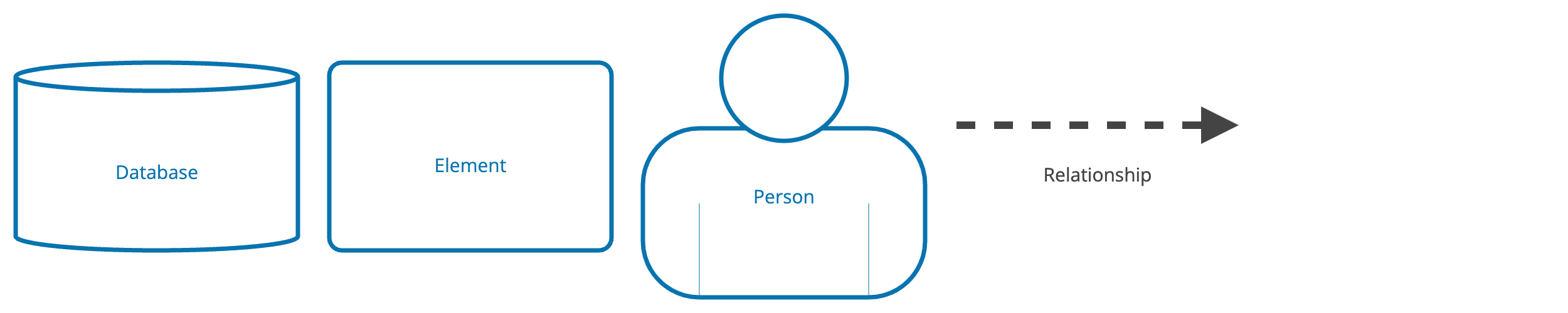
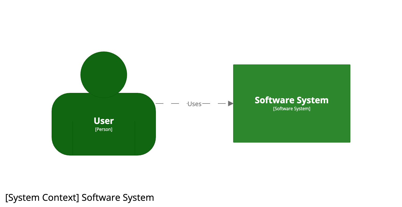
5. Styling elements
Let’s add some colours and shapes to our diagrams. Every element and relationship has a set of text-based tags associated with it - much in the same way that HTML elements can have one or more CSS classes. All elements have an Element tag, while people additionally have a Person tag, software systems have a Software System tag, and containers have a Container tag. Styling elements can be achieved by creating an element style for a given tag.
    views {
        ...

        styles {
            element "Element" {
                color #0773af
                stroke #0773af
                strokeWidth 7
                shape roundedbox
            }
            element "Person" {
                shape person
            }
            element "Boundary" {
                strokeWidth 5
            }
            relationship "Relationship" {
                thickness 4
            }
        }
    }
This code:
- sets the foreground colour and stroke of all elements to #0773af (blue)
- sets the shape of all people to a person shape
- increases the line thickness for boundary boxes (e.g. the dashed line that shows the software system boundary on a container diagram)
- increases the line thickness for relationships
Changing the shape of the database schema element is a two-step process. First we need to add a custom tag (in this case Database to the element).
        ss = softwareSystem "Software System" {
            wa = container "Web Application"
            db = container "Database Schema" {
                tags "Database"
            }
        }
And then we can define an element style for that Database tag.
        styles {
            ...
            element "Database" {
                shape cylinder
            }
        }
Clicking the “i” button inside the diagram editor will reveal the automatically generated diagram key for that particular diagram.